The theoretical efficiency of the new HT class E PA is 8904. Power Amplifiers Purpose of a power amplifier Generate high output power Efficient conversion of DC power to RF power Linear amplification Generally PAs will be Common source Cascode Inductor is a choke to provide D apacitor is a ac coupling path to output James Buckwalter 2.
Diagram Of Class D Audio Power Amplifier Download Scientific Diagram
The introduction of solid-state RF power devices brought the use of lower voltages higher currents and relatively low load resistances.
. At the core of every class D amplifier is at least one comparator and one switching power stage. In all but the lowest-cost. High-Efficiency Wideband RF Power Amplifier with Electronically Tunable Resonant Network.
A high efficiency RF power amplifier is disclosed in which a field effect transistor is operated in a class F mode. Part 1 Class A Device Limitations Large signal output match Define efficiency power-added efficiency Class A operating conditions Thermal resistance We have studied the design of small-signal amplifiers. Most important parameters that defines an RF Power Amplifier are.
Ad CW and Pulsed High Power to 6Ghz. Sokal IEEE Life Fellow Design Automation Inc. DC supply voltage 6.
By comparing PA bias approaches can evaluate the trade-. The efficiency of Class C amplifiers can be fairly high up to about 70-80 but because the distortion is also high 10 to 30 the Class C approach cannot be used for audio. CLASS-E HIGH-EFFICIENCY RFMICROWAVE POWER AMPLIFIERS.
A circuit using the ZVS equations. ECE 145A218A Power Amplifier Design Lectures Power Amplifier Design 1 52407 1 of 18 Prof. This paper presents a high-efficiency current mode class-D CMCD power amplifier for the 1356 MHz band using a Guanellas 11 transmission-line transformer and filtering circuits at the output network.
4 Tyler Road Lexington MA 02420-2404 U. Modules and Systems Multi Kilowatt. In this paper the losses in a Class-D RF switching power amplifier and their frequency dependence are described.
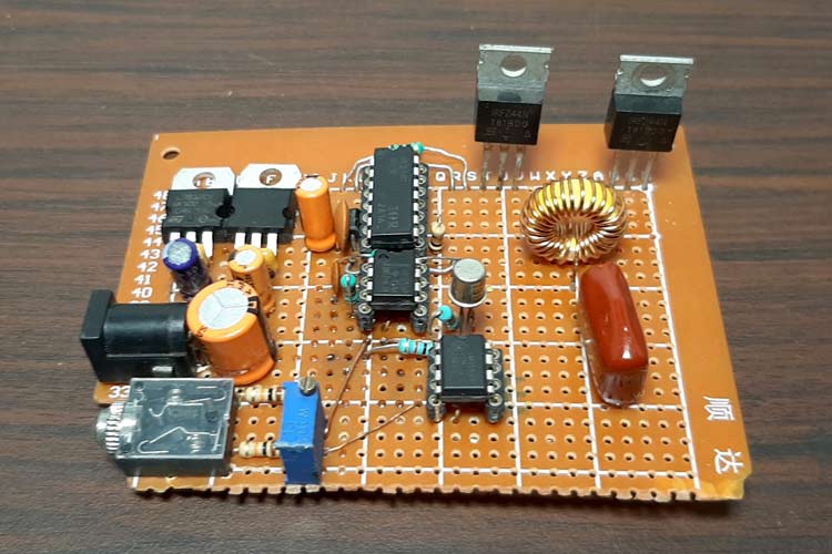
This article describes how to design a simple class D power amplifier using the High Voltage GreenPAK IC. And broadband frequency response. Most important parameters that defines an RF Power Amplifier are.
Multi-Kilowatt Pulsed and CW with Accurate Power Metering and Rugged Design. This thesis presents a high-efficiency Class-F power amplifier PA operating from 30-88 MHz through the use of an electronically tunable resonant network. To the converged power amplifier architecture to reduce the number of power amplifiers within the handset while covering all standards and frequency bands around the globe.
RF output high efficiency power amplifier digital signal processor local oscillator supply voltage amplifier I Q I Q di gi ta l b a s e band i npu t. The losses analyzed are the switching conduction and gate drive losses. A drain efficiency of 87 was achieved at the required power level and fre-quency.
This article presents the design and devel-opment of a high efficiency RF PA design from the perspective of a practicing RF engineerThe PA evolved from a development project. A third harmonic quarterwave open circuit transmission line stub having a Z O adjusted to provide capacitance series resonant with transistor inductance at the second harmonic is coupled to the transistor output lead to produce a low impedance at the channel. A 300 W 1356 MHz Class-D circuit is designed in the traditional manner to illustrate the magnitude of the different types of loss.
The losses analyzed are the switching conduction and gate drive losses. References 1 P. The second and third s are filtered out in the load network of the class-D amplifier.
A class D amplifier operates by deriving a two-state signal from a continuous control signal and amplifying it using power switches. RF Power Amplifier Design Markus Mayer Holger Arthaber. Three main areas of interest in power amplifier design are investigated.
Design of high-efficiency RF Class-D power amplifier. Cripps RF power amplifier for wireless comm2nd edition artech house microwave library 3 Class D Audio Amplifier with Ferroxcube Gapped Toroid Output Filter Ferroxcube. Adshelpatcfaharvardedu The ADS is operated by the Smithsonian Astrophysical Observatory under NASA Cooperative Agreement NNX16AC86A.
PRINCIPLES OF OPERATION DESIGN PROCEDURES AND EXPERIMENTAL VERIFICATION Nathan O. Power efficiency curves of a Class D output stage optimized for maximum efficiency to a single modulation index at different modulation indexes. In this paper the losses in a Class-D RF switching power amplifier and their frequency dependence are described.
In this paper we present design implementation and characterization of a high efficiency radio frequency RF power amplifier PA for S-band telemetry subsystems. Ruggedness Choosing the bias points of an RF Power Amplifier can determine the level of performance ultimately possible with that PA. A 5 W 150 MHz design.
Practical Aspect of RF and Microwave Power Amplifiers 239 Chapter 7. The implemented CMCD power amplifier exhibited a power gain of 134 dB and a. No d Class F hHCA 87-5dB 9 dB.
DC supply voltage 6. However it is used for higher-power RF transmitters where dissipation must be kept to acceptably low levels. ABSTRACT Class-E power amplifiers 1-6 achieve significantly higher efficiency than for conventional Class-B.
Based on this theory a power amplifier is designed using a CREE GaN CGH40010F. The circuit employs a commonly used. High Voltage High Efficiency MOSFET RF Amplifiers Design Procedure and Examples Introduction With the improvement in high power MOSFETs of late lower gate charge low loss gate structures and much improved frequency capability it has become more possible to employ these switchmode devices in rf generators at medium hf.
High Efficiency Power Amplifier Design 247 Overdriven Class B 247 Class F Circuit Design 250 Inverse Class F 264 Class E with Shunt Capacitance 271 Class E with Parallel Circuit 279 Class E with Transmission Lines 286 Broadband Class E Circuit Design 299 Practical High. The proposed RF PA has been implemented using an AlGaNGaN Hot Electron Mobility Transistor HEMT die and shows 50 W output power with a highly linear power gain in required bandwidth. Limiti High efficiency RF and microwave solid state power amplifier John Wiley Sons Ltd 2009 2 Steve C.
How To Build A High Efficiency Class D Audio Amplifier Circuit Using Mosfets

Pdf Design Of High Efficiency Current Mode Class D Power Amplifier Using A Transmission Line Transformer And Harmonic Filter At 13 56 Mhz Semantic Scholar

How To Build A Class D Power Amp Projects

Pdf Design Of High Efficiency Current Mode Class D Power Amplifier Using A Transmission Line Transformer And Harmonic Filter At 13 56 Mhz Semantic Scholar

Figure 1 From A 13 56 Mhz High Efficiency Current Mode Class D Amplifier Using A Transmission Line Transformer And Harmonic Filter Semantic Scholar

How To Build A Class D Power Amp Projects

Class D Power Amplifier Power Electronics News
Fundamentals Of Class D Amplifiers Maxim Integrated
0 comments
Post a Comment